Sensors for
Environmental Monitoring
A wide range of smart sensors, weather stations, water quality sensors
from Monitor Sensors
| Jump to |
Monitor Sensors weather stations and sensors are exported to: Indonesia, Malaysia, New Zealand, Thailand, Canada, Germany, Korea (Sth), Philippines, Singapore, UK, USA, Vietnam Quality Assurance: AS3900 (ISO 9000)
Special Projects: As well as the standard products shown below, we can provide innovative solutions for special projects. Warranty period: One year. | |
| Weather Stations (separate page) Dial into a weather station and try it!Portable Weather Stations (separate page) |
Lightning Strike Station (separate page)
Rainfall Sentry Pump Controller
(separate page) | |
Sensors - General Gold Line options | ||
Sensor Outputs (this page)Sensor interfaces - for other makes of sensor with voltage, current, freq outputs
|
Water Quality (different page)
| |
Sensors - alphabetical list (this page) Evap
|
Pictures of Meteorological Instruments
(.pdf file 351KB, opens in new window) | |
Data Loggers and HandHeld Readerfor weather stations, environmental, etc
|
Alarm Unit WA1 - connect any 1 or 2 sensors
| |
Software (this page) |
Hand held instruments (Testo) jumps to Testo page
| |
Weather Stations
|  |
Monitor Sensors' new generation of environmental sensors are designed with reliability, robustness, low power requirements and accuracy with added sophistication as follows. They can be used with a weather station or separately. |
Each µSmart sensor incorporates a microprocessor providing
linearised and standardised outputs, 16 bit resolution (1 part in 65,000) and
output signals: analog, ASCII data output/input via serial interface, pulse, control & alarm outputs.
Each unit is provided with a multi-point calibration curve for maximum accuracy across the range.
linearised and standardised outputs, 16 bit resolution (1 part in 65,000) and
output signals: analog, ASCII data output/input via serial interface, pulse, control & alarm outputs.
Each unit is provided with a multi-point calibration curve for maximum accuracy across the range.
All µSmart sensors of a given type have the same specifications and calibration.
This eliminates any need to reconfigure the system when a sensor is changed.
The on-board microprocessor ensures identical performance characteristics.
With many other systems, changeover of a sensor means either recalibration of the system or resetting of parameters in the data logger.
This eliminates any need to reconfigure the system when a sensor is changed.
The on-board microprocessor ensures identical performance characteristics.
With many other systems, changeover of a sensor means either recalibration of the system or resetting of parameters in the data logger.
 Each sensor can now be a stand alone instrument that will monitor, log and control an operation within predetermined limits.
There is no longer any need to have ancillary equipment such as a data logger to store information or carry out control functions.
Sensors have their own embedded menu system so that various sensor parameters can be set using a computer in terminal mode,
e.g. sensor characteristics, thresholds, auto-zero, verbosity (e.g. units text on/off), and other changable parameters.
e.g. sensor characteristics, thresholds, auto-zero, verbosity (e.g. units text on/off), and other changable parameters.
These new instruments provide cost effective monitoring solutions for markets from the agricultural and environmental sector to the process and control industry.
Features of the µSMART range of sensors
Sensor outputs can be
analog V or I out (not both), frequency, or Monibus (0-5v TTL serial data, see description below).
When used in the weather stations, the Monibus output is used to connect the sensors to the data logger.
The Monibus output is easily converted to RS232
for connection to computers or telemetry equipment (See SI8 and SI-8 below).
Sensors can be made with two control (digital) outputs.
These are called Goldline Sensors (see further down).
These are called Goldline Sensors (see further down).
- 16-bit resolution (1 part in 65000)
- Sensor cable can be 3-wire or 4-wire. Two wires are for ground and power (5-28 volts), leaving 1 or 2 wires for outputs (see table below).
Cable can extend for 4km. - Can connect many sensors to the same digital signal output wires, daisychain style.
- Menu system in each sensor for setting many parameters. See user manual.(jumps to link further down this page.)
- Serial Data Bus capability (Monibus), with up to 250 sensors on the 3-wire Monibus cable.
- Communication over distances in excess of 4 kilometres in bus mode using a three wire system
- Sensors with Monibus output can operate directly into a PC or Laptop
when using a Serial Interface Unit (SI8 or SI-8 See SI8 and SI-8 below). Sensors or sets of sensors with low power requirements can be powered directly from the host computer.
Those applications with higher current requirements can be powered from a power supply which plugs directly into the SI8 unit.
The RS232 port on a 486 computer can supply 1 or 2 sensors. The RS232 port on a Pentium computer can supply 8 or 10 sensors.
- Real time monitoring with a minimum base period of 1 second (in standard configuration).
- Internally, successive rapid readings are averaged for more accurate output, noise blanking filter to exclude spurious readings
- Multiple calibration points (in excess of 100 mostly).
- Sensors automatically log Max, Min and Average
- Low power requirement for solar power applications
- Software controlled on-board temperature compensation where applicable
- Economy mode - current reduces to 700µA between readings
- Average mode - averages since the previous readout
- The analog output (voltage or current loop option) is continuous.
- The digital ASCII character output updates every second.
- Power: 6-28 volts unregulated DC. Current Draw: 0.6mA normal, (4mA for Wind Direction, 7 mA for Water level, PH, conductivity), 13mA when communicating with computer. For I loop output, min power voltage is 12VDC
- Temperature compensation is carried out by software correction to an accuracy of +/-0.1 deg C.
- Linearity of better than .02% converting Voltage, Current, Frequency or Resistance to RS232 ASCII format.
- Real Time Clock (not battery backed)
- Suitable for use with other data loggers when using V or I output
- Weight of typical stainless steel sensor & housing with short cable: 250gm (not packed)
- Master/Slave setup where one sensor can control all the other sensors to minimise current draw in low power requirement applications.
- Sensors can be programmed to carry out other simple mathematical functions such as convert liquid height to Volume or Flow units
- Daisychain Mode: The Monibus outputs of many sensors may be connected to the same cable wires, daisychain mode. The computer polls the first sensor, and it returns its reading via the serial Monibus. The first sensor then polls the next sensor, it returns its reading, then that sensor polls the next sensor, and so on. This avoids collisions on the serial bus, and simplifies programming.
- Various options for data collection including operator initiation via a keyboard, time interval reading set in the sensor, or event initiated reading, e.g. temperature, reaches a preset level. In Windows Terminal, hitting a number key will return a reading from one sensor
- Can connect any two µSmart Sensors to the WA1 Alarm Unit, which has 240VAC, 10A relay output contacts.
- Quality Assurance: third party accredited ISO9002.
- Calibration certificate traceable to NATA is provided with each sensor
- Low temperature ability of the weather stations & sensors, the general specification from the datasheets is -30°C to +70°C. (Both operational and storage). The wind sensorsspecification (without heaters) quotes figures above freezing, in practice, in Tasmania, there has been no problems with these instruments. Heaters can be fitted if required.
- Two Control outputs (digital I/O) and a Timer output. The outputs can be active high or active low
- The Control outputs activate when the signal crosses preset thresholds, hysteresis if required.
They can operate solid state relays and can be used for stop/start control or alarm signals.
The output will drive a 3.5 volt solid state relay directly
or you can use the small 'donkey' relays provided (12V 0.5A) to switch a larger relay to drive a pump, etc., on 240 volts.
The solid state relays or the contact type are fine for AC voltage but you must use a contactor type relay for switching DC voltage. - In Combined Mode, one or both control output is active when the signal is between the thresholds, the other acts normally
- Control/Alarm set points can be either set in software, or hardware for wind dir & speed, special order. Hysteresis if required.
- Timer output can be active from 0.25 sec to 4.75 hours.
- Timer output is triggered from internal clock every 24 hours, or every 4.75 hours, or can be triggered from a signal crossing a threshold.
Timer output can be terminated by a threshold crossing - Master/Slave setup where one sensor can control all the other sensors to minimize current draw in low power applications
- Standard Deviation available on a second channel on Goldline sensors (3 wire)
- Host facility for "Event" sensors such as rain gauges
- On-board data logging optional Many other functions possible
Sensor Outputs Sensors can have either a 3-wire or 4-wire cable (same price). | |
3-wire cable provides:
ground, power and one signal wire out |
One output only: Monibus serial ASCII output (used in the weather stations, see description below)
Monibus can be converted to RS232 See SI8 and SI-8 below Red or brown: +ve power, White or green : Gnd, Yellow or orange: Serial Monibus |
4-wire cable provides:
ground, power, and two signal wires out |
First output: Monibus Serial ASCII output (see below) (yellow or orange wire)
Second output: Analog output (V or I) or Frequency output (see below) (blue or black wire) Red or brown: +ve power, White or green : Gnd, Yellow or orange: Serial Monibus, Blue or black: analog out |
4-20mA Current Loop output (instead of Voltage Output) can be fitted for additional cost.
The 4-20mA output comes from the 2nd signal output wire of 4-core cable (blue or black), and goes to Ground (the output is not floating). Power voltage range for this is 12VDC to 28VDC. 4-core cable is used: Power (12VDC to 28VDC), Serial Monibus, 4-20mA current output, and Ground. | |
Output Signal Descriptions
Monibus: Serial ASCII output: 0-5v TTL serial data bus.
Can connect many sensors to the same signal output wires. Cable can extend for 4km (has been tested). The host computer uses simple polling (using ASCII character addresses) to read the sensors. Monibus requires only three wires: Signal, Power, and Ground. Sensors can be daisy-chained along the same 3 wires. Monibus to RS232 Converter (jumps further down this page)
The host polls each sensor separately for its readings, or each sensor can poll the next after sending its own data.
The user can access a sensor using a terminal program. Screen shot: click here
Analog output: Voltage 0-1V, or any range up to 4V
(e.g. 0-2.0V is suitable for Anemometer with range 0-200km/h) or 4-20 ma output (additional cost) (Note: Cannot have both Voltage and Current Loop output together.)
Frequency output: 2-10Hz (0-5v TTL)
The µSmart sensors may also be used with Datataker data loggers (opens new tab or window).
|
 The µSmart sensors have mostly stainless steel tube construction,
designed for permanent or semi-permanent fixing.
For hand held instruments (Testo): click here (opens new tab or window)
SI8 Converter: Converts Monibus sensor output to RS232
SI8 Serial Interface Unit, used for interfacing sensors to computer (i.e. no data logger),
with power supply to run the sensors: More data: see further down this page
SI8 Serial Interface Unit, used for interfacing sensors to computer (i.e. no data logger),
with power supply to run the sensors: More data: see further down this page
SI-8 Serial Interface Unit: as above, without power supply (powered from the computer's RS232 port).
More data: see further down this page
More data: see further down this page
µSmart Sensors
|
Sensors have Monibus outputs (see above), and can be daisy chained together.
They can operate directly into a Monitor Data Logger, or into a computer RS232 port via a Serial Interface Unit (SI8 or SI-8)See SI8 and SI-8 below. Sensors may also have Vout, or 4-20mA loop out |
Sensor Wiring:
+ve power: Red or brown Gnd: White or green Serial Monibus: Yellow or orange Analog out: Blue or black |
| Air velocity, fixed or semifixed: Hot wire sensors: these links open new windowsTSI 8455, TSI 8465, TSI 8475 TSI data These have Vout or 4-20mA out TSI product page jdm
Air Velocity meters (hand held):
TSI 9515 9525 9535 9545
|
Gas Sensors: discontinued
Water Quality Sensors:
click here (different page) Conductivity, Diss O2, Redox/ORP, Ion sel, pH, Turbidity, Water Level, Flow. See all of above under Water Quality Sensors
Gas Sensors: discontinued
|
Evaporation Sensor
'A class' evaporation pan (1.2m dia, 300mm deep), µSmart water level sensor, span of 0-200 mm, data logger & accessories. Evaporation in mm. is determined from the drop in water level over the measurement period.
Power source is required (AC mains or solar panel charges the logger battery). Picture: click here
EV1 with manual water refill
EV2 as above, with auto refill 12V 10A contacts are provided for the electrically operated water refill valve (not included). Note: a rain gauge is also necessary, to measure rainfall which may enter the pan during the measurement period. The MM8 Field Equipment Housing & in-ground post is recommended, for the data logger.
Evapotranspiration Virtual Sensor (requires 4 channels in data logger): see below: click here
|
| Leaf wetness sensors LW2: LW2:with 4m cable
or
RD1: Rain Detector Sensor
Data sheet (.pdf)
|
Lightning Strike
Lightning Strike Sensor, 2m cable
Data: click here (.pdf file) LS1: 1.0v/m, LS2: 0.3v/m, LS3: 0.1v/mThe more sensitive lightning sensors may need to be used in pairs with a controller, which discriminates against local electrical interference such as vehicle ignition. LS3 body inc spigot 235mm long. 25.4mm dia, detachable antenna is 590mm long
LP1: Lightning Strike Protector
PK1: Lightning Strike Protector Kit 2 protectors, 2 stakes, copper wire | Lightning Strike ctd.
LA1: Lightning Strike
Alarm Unit
LSS2: Lightning Strike Station
with Data Loggerif using cable >100m, RS232 to RS422 may be reqd Data: click here (.pdf) | pH jump to Water Qual pagePluviometers Rainfall, see below left |
Sensors are arranged in alphabetical order.
Pressure, Barometric
see Barometric above
|
| Relative humidity see Humidity above see Humidity above |
Rainfall: Pluviometer
| Raingauges, Tipping Bucket
for Weather Stations Data
 with 8m cable. Sensitivities: with 8m cable. Sensitivities:µSmart Raingauge. With Monibus output: RG2: 0.2mm/tip, RG5: 0.5mm/tip, Can set the time, reports rainfall since midnight, max rain rate, 9am to 9am total, no of tips in a set period, etc, etc.
Basic Raingauge has reed switch output, or pulse output by using built-in pull-up resistor to +5V, suitable for input to a counter.
RG2-1: 0.2mm/tip, RG5-1: 0.5mm/tip 
Rain Detector
| Sensor Shelters
for air temperature, humidity,
 barometric pressure sensors. barometric pressure sensors.The sensors are strapped with cable ties to an internal vertical bracket (not shown)
Data: click here (opens new window)
SS4 suits 3+ sensors
Internal: 270mm height, 150mm dia External: 365mm height, 285mm dia
SS3 suits 3 sensors
Internal: 230mm x 150mm dia
SS2 suits 2 sensors
 Internal: 200mm x 75mm dia Internal: 200mm x 75mm dia
SS1 for one sensor (small), sensor may be affected by sun
SS6 Aspirated Sensor Shelter
to suit 3 sensors
Note: above part numbers were changed in Feb 2008
|
| Sensor Shelter see above |
| Soil moisture Blocks
PS4: 4 depth Gypsum Block Soil Probe
BL1 Gypsum Block, flat type 60x60x12mm, 2m cable
BL2 Gypsum Block, cylinder type 25mm dia, 50mm long, 2m cable
The gypsum blocks are of a recently improved design, using an imbedded, purpose built, printed circuit board. The dimensions of the electrodes are thus identical in every case. Testing is to verify that the blocks fall within 5% of the standard wetting/drying curves.
CS1 Calcium Silicate Soil Moisture Block, 2m cable
The Blocks are supplied without connectors. 2-pin Conxall connector may be specified |
|
Soil Moisture Hand Held Readers ctd:
MR4: LCD display & Data Logger (stores 120K readings), single sensor types
Sand: These Gypsum block soil moisture sensors do not work well in sand. Please enquire.
|
 Soil moisture sensors
Sap Flow
SF1 Sap flow computer module
SF2 Sap flow computer module |
SV3 Sap velocity computer module (30)
SV4 Custom TDP - 4 Channel Sap velocity Interface - 5 Mtr Cable SV5 Sap velocity computer module (50) SV8 Sap velocity computer module (80) SV10 Sap velocity computer module (100) |
Gro·Point™ Soil Moisture sensing instrument
GP1 Gro-Point Soil Moisture Sensor with µSmart Interface
Gro·Point™ is a cost-effective, moisture-sensing instrument that provides accurate measurement of moisture by volume for most agricultural soils. Gro·Point™ responds immediately and accurately to changes in soil moisture.
The head is designed to remain in the soil for the growing season or on a permanent basis. The µSmart Interface is attached to the head when readings are required or can remain there permanently.. The Gro·Point™' standard moisture sensor provides accurate soil moisture measurements and irrigation techniques that can help growers to improve crop yield and quality while conserving water.
The Gro·Point™ Soil Moisture Sensor operates on a similar principle to radar and is very sensitive to soil moisture surrounding the probe. This is the simplest and most accurate method of measuring water content in soil. Gro·Point™ is rugged, easy-to-use, maintenance free, and responds immediately to soil moisture changes. Manufactured in stainless steel with all electronics sealed in waterproof epoxy, the Gro·Point™ instrument provides years of reliable service.
Data on Gro-Point Sensors: click here |
|
PR1: PAR Cosine corrected solar radiation sensor
400 to 700 nanometres with 2.1m cable
CN1R: Net Pyrradiometer,
also requires V01 Precision V to freq converter CN3: Heat Flux Plate with µSmart interface CA1: 500mm Crop Canopy Absorption Sensor CA2: 1m Crop Canopy Absorption Sensor |
Temperature Sensors
Data on Temperature Sensors (.pdf file new)
TA1 Standard Sensor -40 to +60°C, 0.8m cable
TA1-V1 0…1 volt output acc ±0.1°C between -20 to +60°C TA1-V2 0…2.5 volt output TA1-A4 4…20 mA output TA1-F 2…10 Hz TTL
TA1-C Hi/Low control
TA1-CV1 Hi/Low control + 0…1 volt output TA1-CV2 Hi/Low control + 0…2.5 volt output TA1-CA4 Hi/Low control + 4…20 mA output
TA1+PT100: has small PT100 sensor element on a 1m wire extended from the TA1 unit.
TA2 Wet & Dry Bulb Temperature Sensor,
includes Bottles & Wicks, 0.8mtr cable TB1 Black Globe Temperature Sensor, 4 mtr cable
TG1: Grass, 4m cable
TL1: Leaf, with 4m cable, or
TL1/Fruit: Fruit probe has two parts, the body containing the electronics, and the tip, 3.5mm dia x 10mm long, connected to the body by 1.5m thin wire. Fruit probe has pointed end for pushing into fruit. There is a "pull-out" wire for removal from the fruit. TL1A: Leaf Temperature Sensor, 15 mtr cable
TS1: Soil, 4m cable
TM4: 4 channel temperature sensor.
Requires a TT2 temperature probe for each temperature channel.
TT2: Temperature tip for TM4 multi channel temperature sensor
-20 to +150°C, Acc ±0.1°C. 1 required per channel, 1 metre cable, unless otherwise specified. |
TS1: Soil Temperature Sensor, 4 mtr cable
TT-4: Thermocouple Interface, 5 mtr cable
TW1: Water Temperature,
see Water Quality page: click here Animal Stress Index and Accumulated Heat Load
TB1: Black Globe (Heat Stress) Picture of TB1
The Black Globe thermometer consists of a standard TA1 thermometer clamped to a 152mm (6 inch) diameter, Black Globe, made of copper, so that the tip of the TA1 is at the centre of the Black Globe. (see photo attached). The range and accuracy etc. is therefore exactly the same as for a TA1, except that the serial number begins TB1. The overall height of the instrument with the TA1 fitted is 308mm. The TA1 temperature sensor is clamped to the collar of the Black Globe with an Allen key screw for easy assembly. If the TA1 is mounted in the normal manner, the Black Globe does not require any additional support. The Black Globe must, of course, be mounted where it receives the full sun. The Black Globe, in conjunction with other sensors, is used by the logger to calculate the Animal Stress Index and Accumulated Heat Load Index. |
For information common to all the sensors, see the description near the top of this page
Sensors are arranged in alphabetical order.
Sensors are arranged in alphabetical order.
| Tipping Bucket Raingauges
see "Raingauges" above
|
Voltage Sensors, unipolar or bipolar, VO1/2/3/4ranges 0.1mV up to 1000V. See below
Common mode ranges up to ±10V, opt ±100V CMR 80 to 90dB. 2m cable standard Outputs: Monibus, frequency or Voltage to 4V |
Water Quality Sensors
click here (jumps to different page) Conductivity, Diss O2, Redox/ORP, Ion sel, pH, Turbidity, Water Level, |
Water Level Sensors - Passive Pressure Data: click here (opens new window)
WL1: 0-1m WL2: 0-2m WL3: 0-5m these need cable, WL4: 0-10m see next panel below WL5: 0-20m More info: click here (opens new window of tab)
WL7: 0-200 mm. For use with Evap. Pan
WL8: 0-500 mm. For use with Evap. Pan 5m of 8-core vented cable is included with sensor. You need enough 8-core vented cable on the sensors to bring the cable above the highest water level. It is terminated in a vent housing. The vent housing is part of the overall price of the unit. The rest of the distance to the logger is run in three core cable. . | ||
Wind Speed
 see Anemometers above
Wind Characteristics Station &
Wind Alarm - see on Weather Station page |
WD2 2.1m cable,
or WD3 & WD4 WD Sensors are the only ones which do not have a menu system for setting the various parameters. These must be set in the factory before delivery. Mounting details: click here Model WD3 and WD4 use two separate channels in the data logger
WD3: Wind Direction Sensor with sine & cosine output for sigma theta calculation & standard deviation with wind direction splitter (req 2 channels on data logger)
WD4: Wind direction Sensor, Angle and sigma theta, 2.1mtr cable, includes vane (Note: this will require 2 channels on Logger to operate) Data
| |
Ultrasonic Wind Speed and Direction Sensor - ice free - no moving parts
for wind speed and direction - Vaisala click here (jumps to Vaisala page on this site) | ||

For information common to all the sensors, see the description near the top of this page
Monibus Sensor Installation & Operation Manual Information for Standard Sensors (.pdf file, 14 pages)
Sensor User Manual: click here (.doc file 124KB) explains the menu system in each µSmart sensor
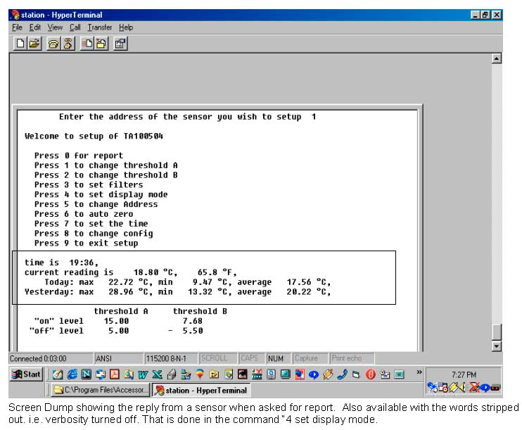
Sample Setup Menu for a µSmart Sensor
Welcome to setup of TA100036
Press 1 to change thresholds Press 2 to set time |
Press 3 to set filters
Press 4 to set mode Press 5 to change Address Press 6 to auto zero Press 9 to exit setup |
Monibus Protocol details
Wiring: Red or brown: +ve power, White or green: Ground, Yellow or orange: Serial Monibus, Blue or black: analog out
Quality Assurance: third party accredited ISO9002.
The µSmart sensors may also be used with Datataker data loggers by using the voltage output option.
The µSmart sensors may also be used with Datataker data loggers by using the voltage output option.
Sensors with Monibus output can be daisy chained together and can connect
either to a Monitor Sensors Data Logger,
or directly into a PC or Notebook computer via a Serial Interface Unit: SI8 or SI-8.
either to a Monitor Sensors Data Logger,
or directly into a PC or Notebook computer via a Serial Interface Unit: SI8 or SI-8.
Virtual Sensors: values are calculated by the data logger from readings of other sensors
Evaporation or Evapotranspiration Virtual Sensor: Evapotranspiration may be calculated by the data logger.
Choose between Priestly-Taylor formula or the Penman/Monteith formula for evaporation calculation.
Requires: Temperature and Solar Radiation sensors, also desirable: Humidity and Wind speed (4 channels into data logger).
Choose between Priestly-Taylor formula or the Penman/Monteith formula for evaporation calculation.
Requires: Temperature and Solar Radiation sensors, also desirable: Humidity and Wind speed (4 channels into data logger).
Other Virtual Sensors to come:
Humidity from Wet & Dry bulb
Dew Point from Wet & Dry bulb, or from Humidity & Temperature.
Humidity from Wet & Dry bulb
Dew Point from Wet & Dry bulb, or from Humidity & Temperature.
SI8 Converter: Monibus to RS232 Serial Interface Unit: for interface to computer,
with power supply to run sensors. Data: click here See notes about command timing below.
It operates at 1200bps only.
It consists of a small box 72x43x27mm with 3 cables coming out, 2 at one end, the 3rd at the other end.. The cables are 0.65m long.
The 3 cables: RS232 with DB9F connector; Power (+ & –, 6-28 volts unregulated DC);
Monibus triple cable (+, –, & serial data)
The SI8 provides power to the sensors attached to it. Large picture of SI8
The SI8 gets this power either from
1) the host computer's RS232 port or
2) a supplied mains adaptor, or
3) 6 - 24V DC unregulated. This could be an external battery.
The SI8 itself uses about 7mA. Add to this the current drawn by the attached sensors.
The RS232 port on a 486 computer can supply 3 or 4 mA. (1 or 2 sensors)
The RS232 port on a Pentium computer can supply 8 to 10mA. (8 or 10 sensors)
Sensor cable length can be up to 4000m.
SI-8 Converter: as above, except is powered from the computer's RS232 port:
A pair of wires are provided for connection of external power supply should the serial port's supply be insufficient. (5V to 20VDC max)
The RS232 port on a 486 computer can supply 3 or 4mA (1 or 2 sensors)
The RS232 port on a Pentium computer can supply 8 to 10mA. (8 or 10 sensors).
A pair of wires comes out of the unit which can be connected to a power source (6 to 24VDC) if required.
Sensor cable length can be up to 250m.
DB9F (25-pin female). SI-8:
Sensor Power Requirements
Water level 7mA, pH 5mA, Turbidity 10 to 16V DC at 15mA (45mA for Model 195 when wiping)
Soil moisture 4mA, Barometric Pressure up to 5mA
Wind Direction 2 mA,
Other sensors use up to 2 mA.
Water level 7mA, pH 5mA, Turbidity 10 to 16V DC at 15mA (45mA for Model 195 when wiping)
Soil moisture 4mA, Barometric Pressure up to 5mA
Wind Direction 2 mA,
Other sensors use up to 2 mA.
Notes about timing of commands:
1) There is no dead time on the Monibus as such. The SI8 itself has no intelligence or storage facility. It passes the messages with negligible delay (a few microseconds). The sensors do have a delay in responding and this is necessary in order to make sure they have received the full command. There is no "end of command" character.
The end of command is indicated by a pause in transmission of approx two bytes duration. At 1200 baud this corresponds to a time of 16 to 20 milli seconds. After this time the sensor decodes the command and sends a reply if necessary.
2) In practice this reply will begin between 22 and 27 milliseconds after the last byte of the command has been sent.
3) The way to make sure that the sensors are ready to receive a new command is to wait for the Monibus to be idle for at least 30 milliseconds. This includes waiting for any responding sensor to finish its message and then wait the additional 30 milliseconds.
NOTE: The sensors do not know the origin of any command on the Monibus.
They will respond to a command from another sensor as well as from the PC or a logger. This is what happens when the sensors are put in daisy chain mode. For example, you could put the TA1 and HU1 in daisy mode. Then you would only need to send the address of the TA1 and both sensors would reply in sequence. You can even pre-determine if this reply is to be on the same line or on three lines.
To use daisy chain mode in its simplest form you will need to have the sensors on sequencial addresses e.g. 2,3,4.
You can turn on daisy chain mode through the sensors' setup menus BUT as soon as power is broken, daisy chain mode will be switched off. If you want PERMANENT daisy chain mode you need to send a special command (ask for details).
4) The sensors can not store commands. They can only handle one command at a time. A string of commands will normally be ignored by all sensors. A gap in transmission of 30 milliseconds will cause the sensors to start to look for a new valid command.
Current Loop Outputs:
4-20mA current loop output can be fitted for additional cost.
Power voltage required for this is 13.6VDC to 28VDC.
Output cable required is 3-core: Power (13.6VDC to 28VDC), 4-20mA current output, and Ground.
4-20mA current loop output can be fitted for additional cost.
Power voltage required for this is 13.6VDC to 28VDC.
Output cable required is 3-core: Power (13.6VDC to 28VDC), 4-20mA current output, and Ground.
Interfacing other sensors to Monibus for use with Monitor Sensors data loggers
The following voltage and pulse converters, V01, V02, etc, are similar to µSmart Sensors, as described near the top of this document, giving the µSmart outputs (Monibus, voltage , frequency). They can make many kinds of instruments and sensors compatible with the Monibus sensors and with Monitor Sensors data loggers.
Voltage - Current - Frequency - Digital I/O µSmart Sensors, can convert the output of instruments or sensors to give µSmart outputs, including Monibus output.
Ranges 0.1mV up to 1000V
Common mode ranges up to ±10V, optionally ±100V
CMR 80 to 90dB. 2m cable standard Outputs: Monibus, frequency or Voltage to 4V.
Ranges 0.1mV up to 1000V
Common mode ranges up to ±10V, optionally ±100V
CMR 80 to 90dB. 2m cable standard Outputs: Monibus, frequency or Voltage to 4V.
V01: Precision Voltage input, single, 2m cable
V02: Precision Voltage input, differential non-isolated, 2m cable
V03: Precision Voltage input, unipolar, isolated to 1.5kV, 2m cable
V04: Precision Voltage input, bipolar, isolated to 1.5kV, 2m cable
V02: Precision Voltage input, differential non-isolated, 2m cable
V03: Precision Voltage input, unipolar, isolated to 1.5kV, 2m cable
V04: Precision Voltage input, bipolar, isolated to 1.5kV, 2m cable
C01: Precision current to µSmart series Converter, single, 2mtr cable
C02: Precision current to µSmart series Converter, differential-non isolated, 2mtr cable
C03: Isolated current to µSmart series Converter, Unipolar isolated to 1.5Kv
C04: Isolated current to µSmart series Converter, Bipolar
C02: Precision current to µSmart series Converter, differential-non isolated, 2mtr cable
C03: Isolated current to µSmart series Converter, Unipolar isolated to 1.5Kv
C04: Isolated current to µSmart series Converter, Bipolar
F01: Precision Frequency to µSmart series Converter, single, 2mtr cable
F02: Precision Frequency to µSmart series Converter, differential-non isolated, 2mtr cable
F03: Isolated Frequency to µSmart series Converter, Unipolar isolated to 1.5Kv
F04: Isolated Frequency to µSmart series Converter, Bipolar
F02: Precision Frequency to µSmart series Converter, differential-non isolated, 2mtr cable
F03: Isolated Frequency to µSmart series Converter, Unipolar isolated to 1.5Kv
F04: Isolated Frequency to µSmart series Converter, Bipolar
SI8: Converter, Monibus to RS232 Interface with 500mA Power Supply for Sensors, see above
SI-8: Converter, as above, without power supply, see above
4-20ma: 4-20 ma option
VF1: Dual voltage free contact board
SI-8: Converter, as above, without power supply, see above
4-20ma: 4-20 ma option
VF1: Dual voltage free contact board
Digital I/O Smart Sensor, 8 channels (channels must be factory set as input or output, specify when ordering)
Analog signal to RS232 Converters:
Interface modules that can take any resistive, voltage, frequency or current input, and convert it to a serial data output in ASCII format.
Interface modules that can take any resistive, voltage, frequency or current input, and convert it to a serial data output in ASCII format.
Current µSmart Sensors CIE: 4 to 20mA input µSmart Sensor
WA1 Alarm Control Unit with LCD display
 WA1 Alarm Control Unit with LCD display (backlit) and push button menu system.
Connect any two sensors, such as wind speed and wind direction - useful on building sites, or temperature & humidity.
If over/under (or both) the preset points it gives either
an audible alarm (beep-beep-beep) or bright Xenon lampflashes (factory setting, specify when ordering).
There is an additional cost if both audible AND visible alarms are required.
Can set time delay before alarm proceeds.
The two channel LCD readout shows an asterisk next to the channel in an alarm condition.
Mount where personnel can see it. Includes mains adaptor. 9-28VDC.
Optionally, Can use solar panel and internal battery.
Picture: click here Right side Left side
These pictures show a unit which has audible alarm (no Xenon lamp), and current loop output terminals for the two sensors (not shown).
Dimensions: Case width 117mm, overall width 140mm, height 216mm including mounting flanges,
depth of case 57mm (allow extra for items mounted on the front).
Data sheet onWind Alarm Control Unit (.pdf)
WA1 Alarm Control Unit with LCD display
Options:
WR1 Relay Output unit, internal, with 240VAC 10A contacts, 2 relays possible,
one relay could be associated with both inputs, or
two relays could each be associated with a particular input. For each relay, add $POA (factory option)
WR1 Relay Output unit, internal, with 240VAC 10A contacts, 2 relays possible,
one relay could be associated with both inputs, or
two relays could each be associated with a particular input. For each relay, add $POA (factory option)
AL1 Alarm Light, 12V rotating beacon for outdoor use
AL2 Alarm Light & Siren, Xenon flashing beacon, and multitone siren
AL3 Alarm Light, high intensity Xenon flashing light for indoor use in large space
AL2 Alarm Light & Siren, Xenon flashing beacon, and multitone siren
AL3 Alarm Light, high intensity Xenon flashing light for indoor use in large space
Hand Held Reader or Reader/Logger
MR1: LCD display (3½ digits), 1 ch reader
MR2: LCD display, auto-seeking, up to 4 ch, can use any µSmart Sensors
MR3: LCD display & Data logger, hand held, auto or demand logging (stores 120K readings), can use any µSmart Sensor.
MR2: LCD display, auto-seeking, up to 4 ch, can use any µSmart Sensors
MR3: LCD display & Data logger, hand held, auto or demand logging (stores 120K readings), can use any µSmart Sensor.
 Monitor Data Loggers: click here
The µSmart sensors may also be used with Datataker data loggers
DM4 Docking Memory Module, holds up to 500K readings, plugs into front of Monitor Data Logger
DS1 Docking Station to download data from DM1 above, to PC
 Hand Held Readers or Reader/Logger
MR1: LCD display, 1 ch reader Large picture of Hand Held Reader
MR2: LCD display, auto-seeking, up to 4 ch, can use any µSmart Sensors
MR3: LCD display & Data logger, hand held, auto or demand logging (stores 120K readings), can use any µSmart Sensor.
MR2: LCD display, auto-seeking, up to 4 ch, can use any µSmart Sensors
MR3: LCD display & Data logger, hand held, auto or demand logging (stores 120K readings), can use any µSmart Sensor.
MR1 Single Channel Hand Held Reader battery powered
MR2 Multi -Channel Hand Held Reader battery powered
MR1 & MR2 were originally designed for the soil moisture sensors, however they may be use with any sensor.
The MR1 and the MR2 portable readers offers an option for measuring and monitoring soil moisture at a large number of points across a farm.
The sensors are permanently inserted in the ground and the hand held reader is used to access the information at regular intervals.
The LCD display on the reader is used to manually record the soil moisture readings at the different points.
MR3 is a reader logger and provides both LCD display and automatic logging of the data that can be downloaded from the reader on return from the field. The logger can record and store up to 120,000 reading.
MR series include internal 6V Gel Cell battery and charger 240VAC
LCD Displays
A service tool for testing sensors.
Each channel has its own 16 character LCD display, (height of characters: 6.5mm).
Any number of these can be mounted in a suitable sized case.
Uses the Monibus output (ASCII text) from sensors.
Note: the Data logger case is normally fitted with one LCD panel. The various channels can be observed by scrolling.
Any number of these can be mounted in a suitable sized case.
Uses the Monibus output (ASCII text) from sensors.
Note: the Data logger case is normally fitted with one LCD panel. The various channels can be observed by scrolling.
LCD1: Single channel LCD real time display, c/w power supply or battery .
LCD2: Dual channel LCD real time display, c/w power supply or battery
LCD3: Three channel LCD real time display, c/w power supply or battery
LCD4: Four channel LCD real time display, c/w power supply or battery
LCD5 /6 /7 /8 five ot 8 or more channels
LCD2: Dual channel LCD real time display, c/w power supply or battery
LCD3: Three channel LCD real time display, c/w power supply or battery
LCD4: Four channel LCD real time display, c/w power supply or battery
LCD5 /6 /7 /8 five ot 8 or more channels
The above displays may be connected to a modem
using the SI8 Converter (see above) which includes 500mA power supply for sensors.
An extra connector can be fitted to the LCD Display case for this purpose, at no extra charge.
Power: internal battery: 9V PP (small rectangular) or can run from 9VDC power supply (not included).
using the SI8 Converter (see above) which includes 500mA power supply for sensors.
An extra connector can be fitted to the LCD Display case for this purpose, at no extra charge.
Power: internal battery: 9V PP (small rectangular) or can run from 9VDC power supply (not included).
Software for PC
Download SmartLogger.exe Software for downloading the data fromThe SmartLogger software is a basic program to help with downloading data from Monitor SmartLoggers,
graphing it, or saving it to an Excel file.
It also works through a GSM or dial-up modem connection.
graphing it, or saving it to an Excel file.
It also works through a GSM or dial-up modem connection.
Using a Terminal program
The µSmart data loggers, and the sensors (without a data logger), can be downloaded and controlled using a terminal program
(e.g. Windows HyperTerminal included with Windows 95, 98, XP, etc),
for setting up, unloading data in readable text format and storing to disk.
The user can access a sensor using the Windows HyperTerminal program. Screen shot: click here
SmartLog - new Windows Software searches for and finds sensors automatically,
either when connected to a Monitor Sensors data logger, or when connected to the serial port via SI8 (Monibus to RS232 Converter).
It logs data from sensors to disk in CSV text format which can be readily imported into spreadsheets or
data can be linked by DDE directly into applications such as a spreadsheet.
Trend plotting, etc, can then be done in the spreadsheet.
It also displays the most recent readings on-screen, including "dial" and "meter" readouts.
Can generate an SMS message on an alarm condition. (E-mail could be added).Many other useful features.
SmartLog Software:
PCL for when a logger is present or
PCS for when there are only sensors and no logger
Download the User Manual: click here ( .doc file 535KB)
Ethernet Interface Software
Monitor Sensors can supply Ethernet interfaces for the Monitor SmartLoggers,
and server software that can automatically retrieve the current readings and historical data from the logger.
The retrieved data can be optionally merged into a user supplied web page template
and automatically uploaded to a web server by ftp.
Two templates are provided - a current readings table and a web graph page.
The program includes a terminal interface that allows the logger to be customised and the data stored by the logger to be retrieved.
A running log of the program operation is saved regularly to help the user resolve any upload problems.
Data on Ethernet Interface Software (.pdf file 750KB, opens new window)
GPRS interface to our sensors and loggers
We also have been working on a GPRS interface to our sensors and loggers.
This allows a group of sensors or logger to connect to server software over the internet using a GSM/GPRS modem.
This allows realtime data at a cost of about 10c a packet.
This allows a group of sensors or logger to connect to server software over the internet using a GSM/GPRS modem.
This allows realtime data at a cost of about 10c a packet.
Software for the older Monitor Sensors loggers:
SDV01 DATAVIEW Software: Time series line & bar graphs for Monitor data.MS-DOS
SWR01 WINDROSE Software: Displays and prints windroses from wind data.MS-DOS
AVMS: AusVit Vinyard Management System:
AVSR: AusVit Vineyard Spray Records
AVCDB: AusVit Vineyard Chemical Database
AVB1: Vineyard block licence:
SDP01: Datapoll software
SEP-01: EPROMs for old loggers:
SCF-01: Configuration files, per hour:
AVMS: AusVit Vinyard Management System:
AVSR: AusVit Vineyard Spray Records
AVCDB: AusVit Vineyard Chemical Database
AVB1: Vineyard block licence:
SDP01: Datapoll software
SEP-01: EPROMs for old loggers:
SCF-01: Configuration files, per hour:
For upgrading old loggers, LOGGER Utilities upgrade, Windows 95 or 3.1 is available:
Electronic Pluviometer
Electronic Pluviometer combines a Rain gauge with a battery powered data logger
with 512K RAM (120K readings), giving storage for years.
Serial port for interface to computer, printer or modem.
Includes 6v rechargeable GelCell sealed battery, lasts for about 6 months without recharge.
Battery voltage monitoring is provided.
Data on the Pluviometer Data Logger (.pdf file, opens in new window)
Data on Electronic Pluviometer (.pdf file, opens in new window)
Data on the Tipping Bucket Raingauge (.pdf file, opens in new window)
Other sensors - please enquire
Esis Pty Ltd 02 9481 7420 Fax 02 9481 7267 www.esis.com.au E-mail: click here Esis main page


Nowadays we use the devices which have built-in sensors, though the internet temperature sensor we can handle environmental conditions easily through sensor from anywhere. Your blog provides knowledgeable information about the different type of sensors, thank you to sharing this information with us.
ReplyDelete